The sketching with hardware course is the entry point to learning how to build functional interactive systems that do not conform to the usual form factor!
The teaching approach is “hands-on” and we start with doing and then later discuss why it is working and what we need to know to understand why it works. For Arduino there are plenty of tutorials out there and the following tasks should make an easy start.
Install an IDE
First search for the Arduino IDE (the development environment) and install it on your computer. We recommend starting with the download version (https://www.arduino.cc/en/main/software). There is also a web version and other IDEs, which are more powerful but also more difficult to get started (e.g. https://platformio.org/ )
LEDs and output
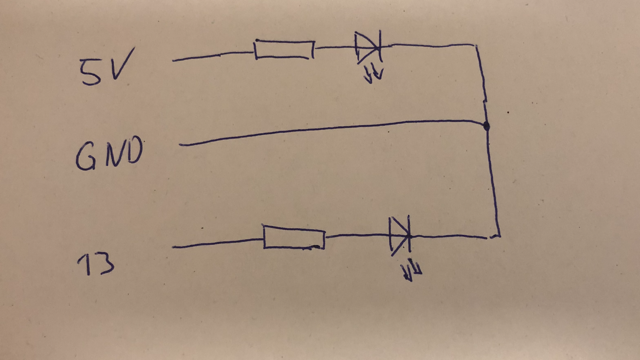
- Connect an LED and a resistor (220 Ohm) between the 5V and GND. Which direction do you have to put the LED in? Remember the “long” leg is in the direction of + (plus is made of two strokes, minus only of one, hence plus is the longer one).
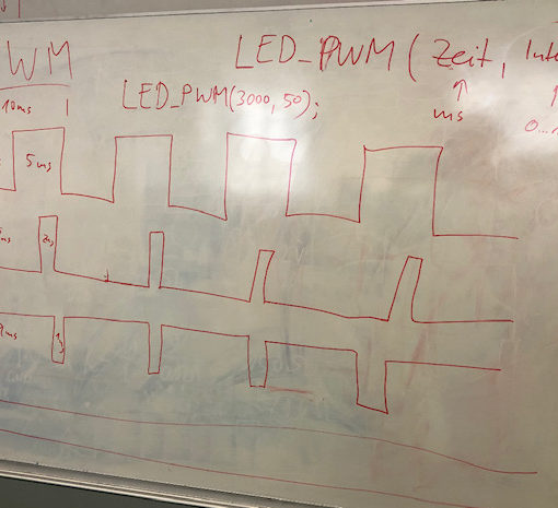
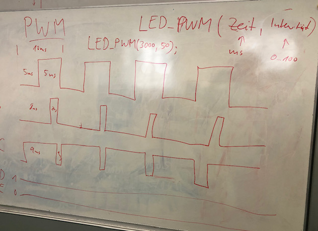
- Connect an LED and a resistor (220 Ohm) between D13 (a digital output) and GND. Find an example program for Arduino that makes the LED blink. Change the timing of the on and off time.
Serial print and debugging
Have a look at how to print on the serial line with Arduino: Serial.println() and how you can see the print out on the serial monitor in the IDE. Write a loop that counts upwards and prints the result on the serial console.
Digital input and buttons
- configure one of the inputs (e.g. D6) as digital input and read the value with digitalRead()
- print the value you receive on the serial console
- use us a wire to connect the input to 5V or to GND and check what value you get
- search for an example on how to connect a button or a switch to the Arduino and read in the value
- read up (or watch a tutorial) what a pull-up and pull-down resistor (or flag is good for)
Analog input
Look for an example of how to read in an analog value. Connect a potentiometer between 5V and GND with the middle pin to an analog input (e.g. A1). Read the analog value and print it on the serial line.
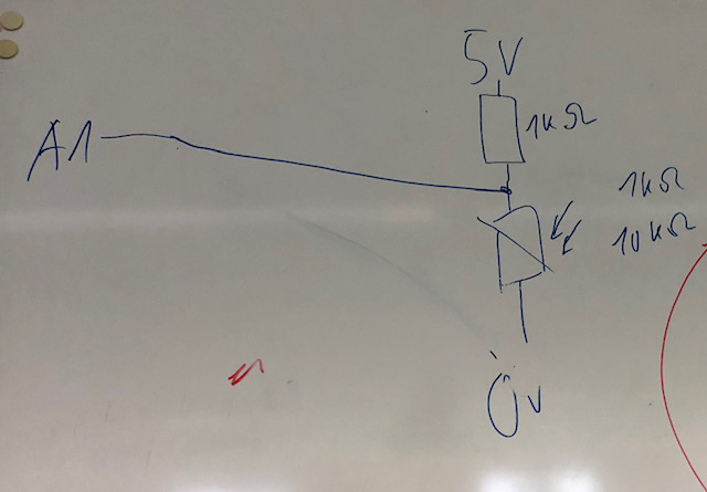
Try to understand how a voltage divider works. If you have a sensor that changes its resistance with measured value (e.g a force-sensitive resister FSR or a light sensitive resistor LDR) you have to put them in row with a fixed resistor in order to measure the voltage and voltage change. Why do you need a voltage divider in this case? How do you decide on the resistance of the fixed resistor?
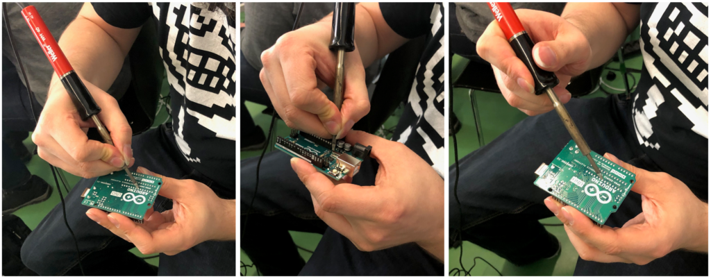
Soldering
Everyone gets an introduction soldering in the lab. You can also look on Youtube for a good tutorial. It is important to heat up the PCB as well as the component. You should melt the solder on the component/PCB not on the soldering iron. Here are two pictures that sketch how it should look like if it worked (solder is pulled in to the hole) and how it looks if it did not work (solder sits on top).
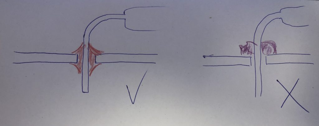
Two of the following pictures are showing a seriously wrong approach to soldering – if you do not see what is wrong in two of the picture, please do not touch the soldering iron!
